
Circuit Design
-
Getting Raw Data from a Taxel
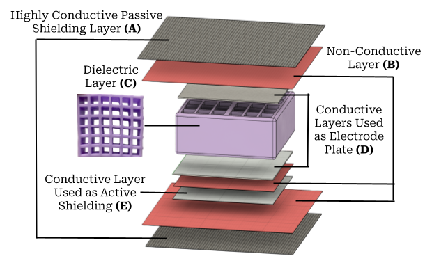
(1) Layer Functions:
-
Highly Conductive Passive Shielding Layer (A): connects to ground, serves as the passive shielding layer, and uses physical barriers to prevent electromagnetic interference.
-
Non-Conductive Layer (B): doesn't connect to anything, serves as a spacing layer. It is used to separate conductive layers to prevent them from touching each other and causing a short circuit.
-
Dielectric Layer (C): doesn't connect to anything, serves as the dielectric in a capacitor.
-
Conductive Layers used as Electrode Plate (D): the upper D layer is connected to ground, the lower D layer is connected to one of the CIN pins on the FDC1004 convertor, which serves as the electrode plates in the capacitor. Two D layers and one C layer together function as a capacitor. When the contact happens, deformation will take place on the taxel in axial direction, thus, the distance between two D layers will change, which leads to the change of the capacitance value. We can then get the force exerted by the contact using the capacitance value of the taxel.
-
Conductive Layer used as Active Shielding (E): connects to ground through a 51pF capacitor and serves as the active shielding layer. The layer is used to generate signals that counteract the unwanted external interference.
To read more about active shielding, please see the document here.
(2) CDC Board:
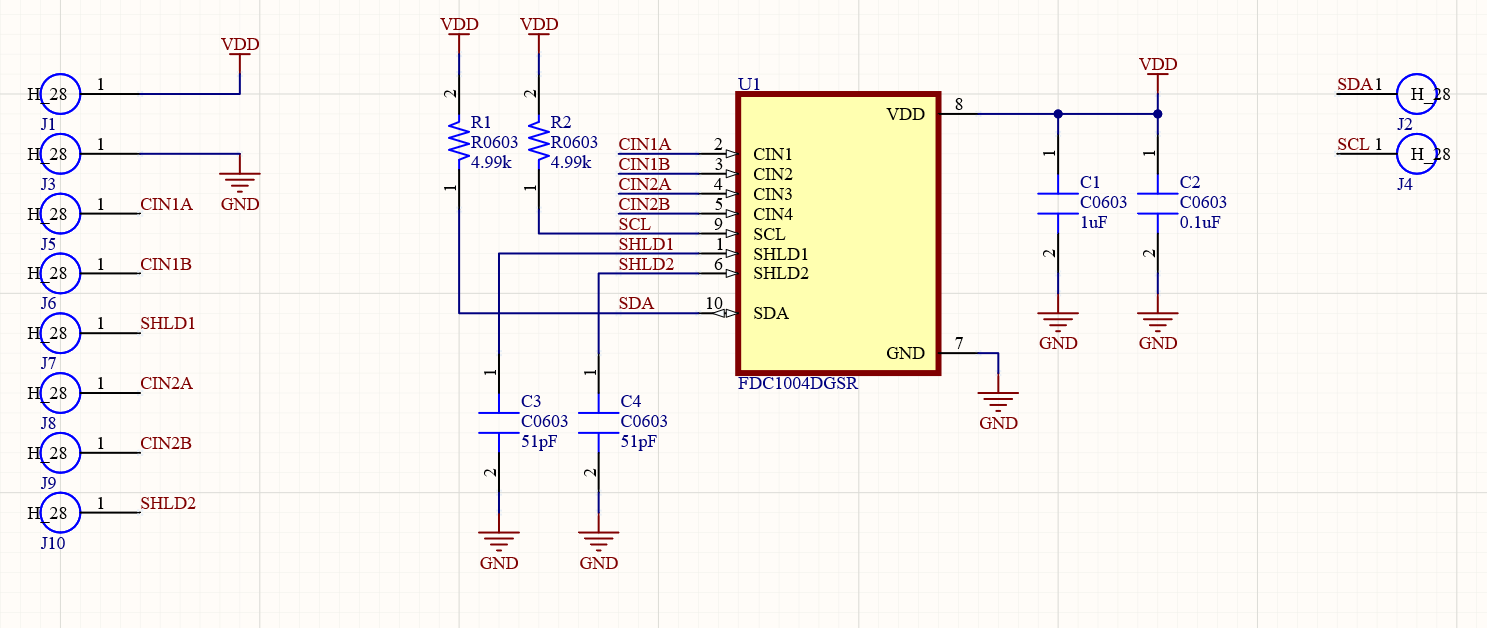
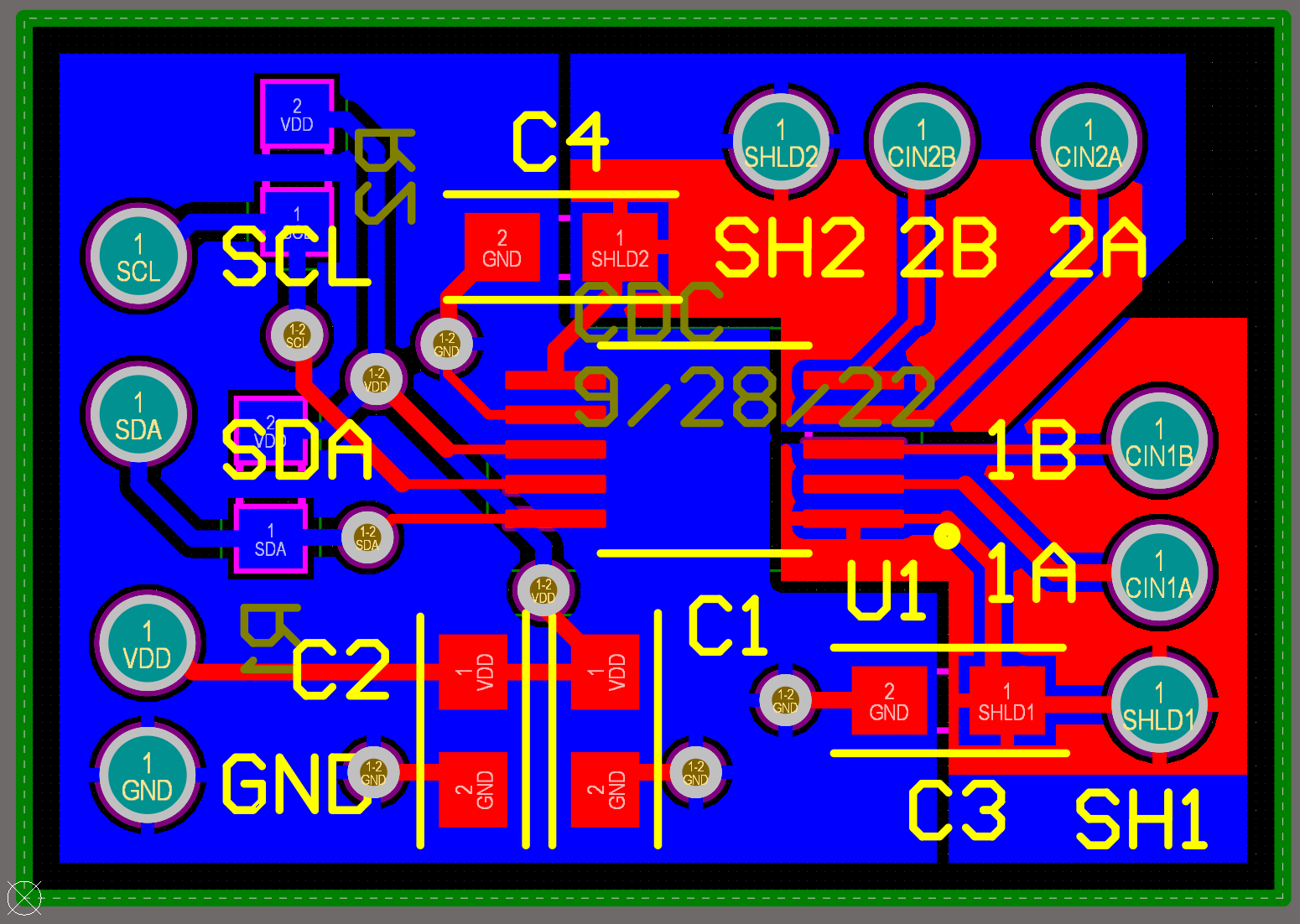
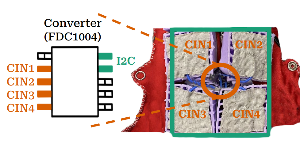
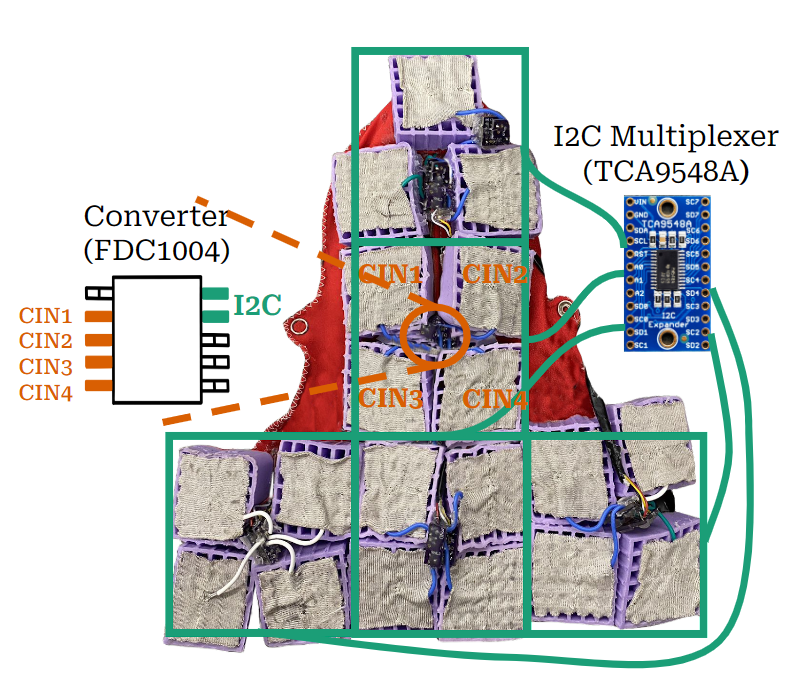
We designed a PCB board which uses the FDC1004 chip to convert the capacitance data sensed by the taxel to digital data. FDC1004 is a high-resolution, 4-channel capacitance-to-digital converter for implementing capacitive sensing solutions. Each channel has a full scale range of 15pF. FDC1004 also includes shield drives for sensor shields, which can reduce EMI (Electromagnetic Interference) and help focus the sensing direction of a capacitive sensor. Furthermore, it features an I2C interface for an MCU.
buy FDC1004 here see document for FDC1004 here
We used the PCB boards to convert the data sensed by 4 taxels. The boards transfers data to the Arduino board through the I2C protocol.
2. Data Communication via Daisy Chain Connections
(1) Daisy Chain Implementation in I2C:
We used a daisy chain structure to connect multiple I2C devices together on the same bus. Each device has a unique address, and they communicate with the micro controller over a shared set of wires. (SCL for clock, SDA for data)
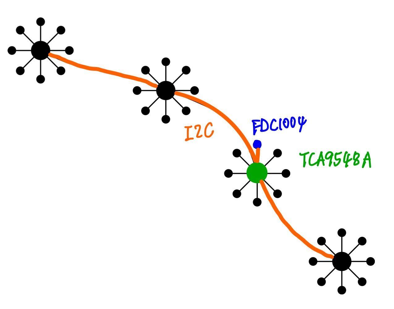
(2) TCA9548A (8-channel I2C Switch):
The TCA9548A multiplexer has 8 bidirectional translating switches that can be controlled through the I2C bus. The SCL/SDA upstream pair fans out to eight downstream channels. Any individual SCn/SDn channel or combination of channels can be selected, which determines the contents of the programmable control register. These downstream channels can be used to resolve I2C subordinate address conflicts.
We used a TCA9548A multiplexer to read the data for taxels in one link, then use I2C communication to connect the multiplexers of each link in the series. An arduino board is also connected to this I2C bus, so it can read the data of each taxel by specifiying an I2C address and channel.
(3) I2C bus connection
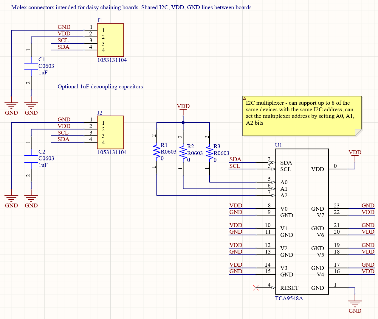
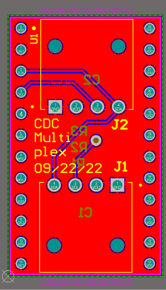
In order to facilitate the multiplexers of different links to access the I2C bus, we designed a PCB board and used molex connectors to connect the boards together.
(4) Arduino Reads data and Publishes it to ROS
From arduino side, we read data like this:
tcaselect(0, TCAADDR1); //scl0 sda0
c[0] = gettaxelreading( ONEB );
Here, we first select the I2C address on the TCA9548A which is determined by the voltage level of the A2A1A0 pin, and specify which channel data on the TCA9548A needs to be read (channel 0 in this case). Then, We specify the number of the pin (ONEB in this case) on the FDC1004 chip that we need to read and read the data into the c[] array.
The complete code can be viewed here
3. Skin Maintenance
-
Cable Management: sew the cables on the inner part of the skin. Since the energized current will have electromagnetic interference, and these cables will inevitably be very close to the taxel, try to fix these cables on the inner part (close to the passive noise reduction layer of the robot arm), so that they can be possibly reduce the electromagnetic interference they bring to the capacity sensor.
-
Use Velcro and Zip Ties: never be stingy about using velcro and zip ties. Use zip ties to tie the I2C communication cables of each link together, and use velcro to fix the multiplexer in place.
-
Dubugging the Circuit: don't try to debug the entire circuit at the same time. This makes finding the error harder. Instead of link by link, check taxel by taxel. For each taxel first view the data printed on the arduino side, and then proceed to the visualization on the ros side.