TACTIC · Open Hardware
Tactile Skin
A WiFi-based 22-taxel piezoresistive sensing suite for the Kinova Gen3.
Overview
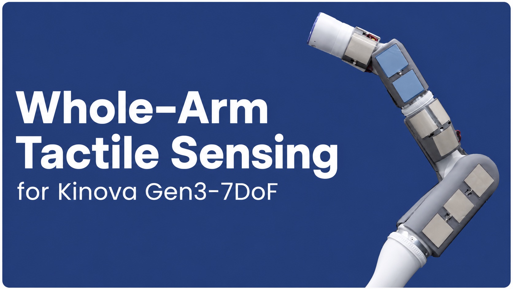
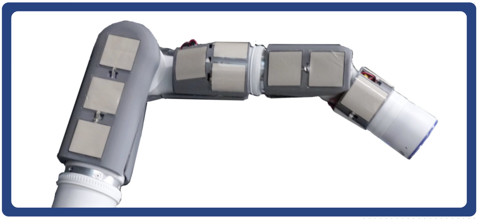
The skin mounts 22 Tekscan FlexiForce A502 sensors across the Gen3's links to measure pressure along the arm: thin, flexible force-sensing resistors with a 50.8 mm × 50.8 mm sensing area per pad that convert applied force into a change in electrical resistance.
The sensors are organized into four mounts: five pads on each spherical wrist joint, six on the forearm link, and six on the half-arm link. Each mount pairs with an Adafruit Feather M0 WiFi board that communicates pressure readings at 800 Hz per board; sensor and mount positions relative to the robot come from CAD model measurements. The boards run on LiPo batteries and report over WiFi, so no cables tether the robot.
Bill of Materials
| Vendor | Part | Unit cost | Qty | Cost | Link |
|---|---|---|---|---|---|
| Tekscan | FlexiForce A502 pads | $27.87 | 22 | $613.14 | Product page |
| Adafruit | Feather M0 WiFi | $39.95 | 4 | $159.80 | Product page |
| Adafruit | 3.7 V LiPo rechargeable battery | $12.50 | 4 | $50.00 | Product page |
| Adafruit | Micro-Lipo charger | $6.95 | 4 | $27.80 | Product page |
| Adafruit | 10 kΩ through-hole resistors (25-pack) | $0.75 | 1 | $0.75 | Product page |
| McMaster-Carr | 302 stainless steel torsion spring | $3.23 | 1 | $3.23 | Product page |
| Amazon | Gorilla clear double-sided mounting tape | $11.99 | 1 | $11.99 | Product page |
| Amazon | JST XH 2.5-2 pin battery connectors (50 set) | $7.79 | 1 | $7.79 | Product page |
| Amazon | Double-sided Velcro | $15.43 | 1 | $15.43 | Product page |
| Total | $889.93 | ||||
Printed Parts
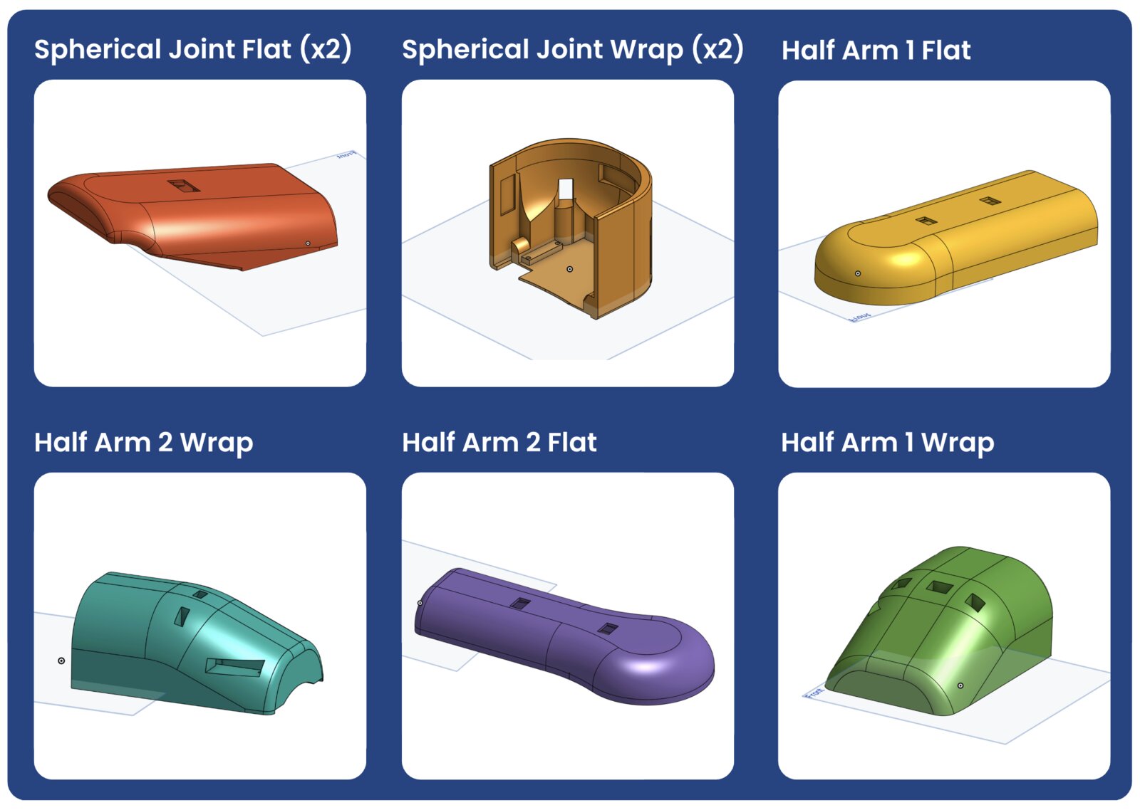
Each mount is shaped to its link, carrying the pads on the outside and the readout board on the inside. STL and CAD files are in the hardware files folder.
Assembly
Step 1 · Wire the pads to the boards
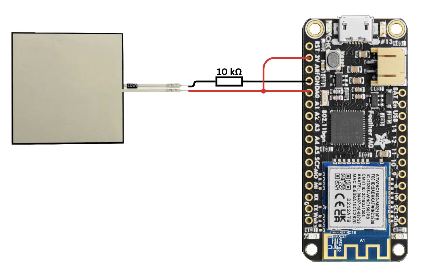
Make up the sensor wires and connect each taxel to its link's Feather board, following the circuit below (each pad forms a voltage divider with a 10 kΩ resistor).
Step 2 · Attach boards to the mounts
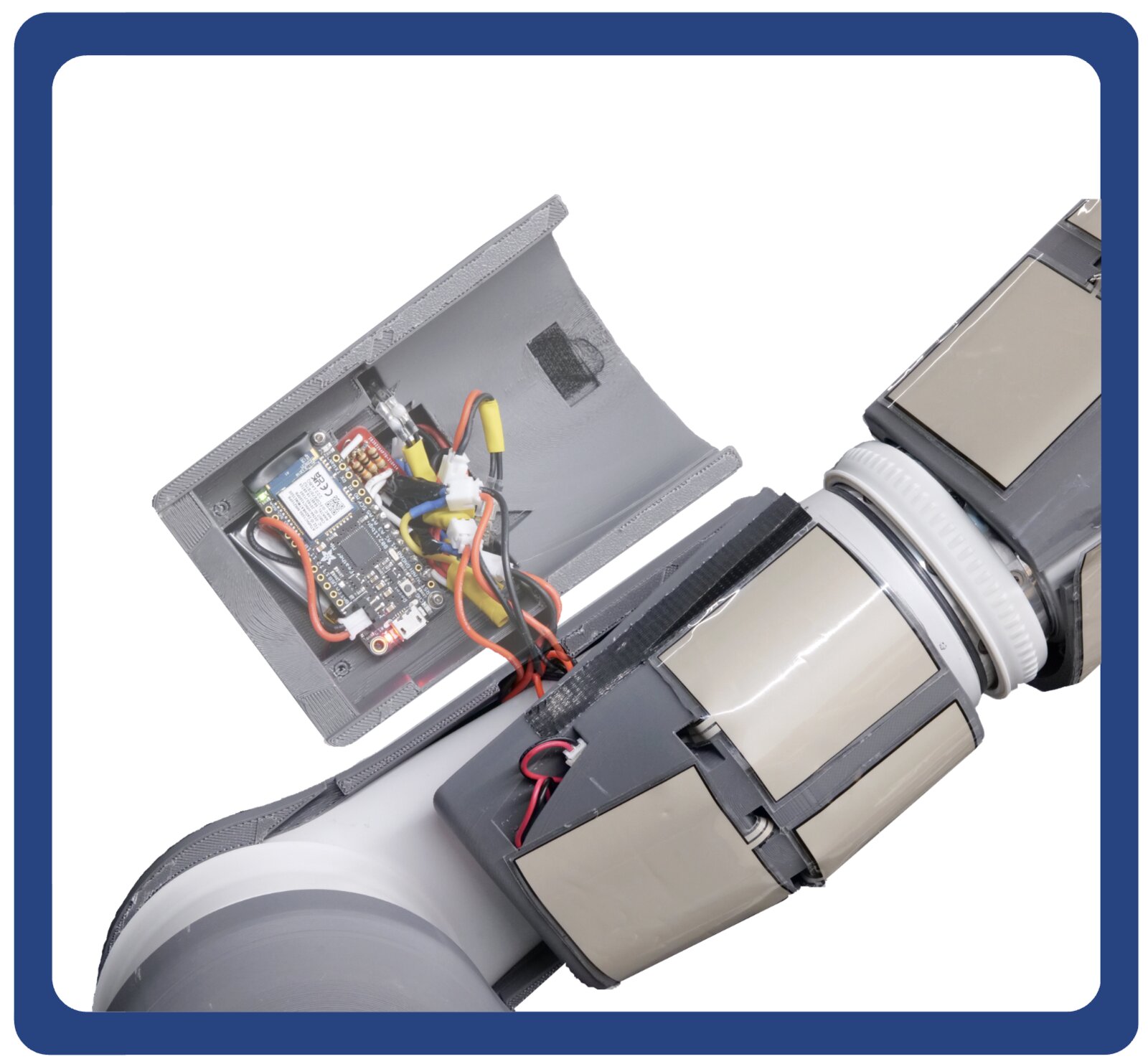
Screw each board onto its mount, then fix the tactile pads to the outside of the mount with the double-sided Gorilla tape.
Step 3 · Fit the mounts on the robot
The longer mounts snap into place on their links. For the smaller mounts, a small strip of Velcro on the inside holds them to the robot if needed.
See also: the leader-arm teleoperation interface used alongside this skin to collect whole-arm demonstrations.